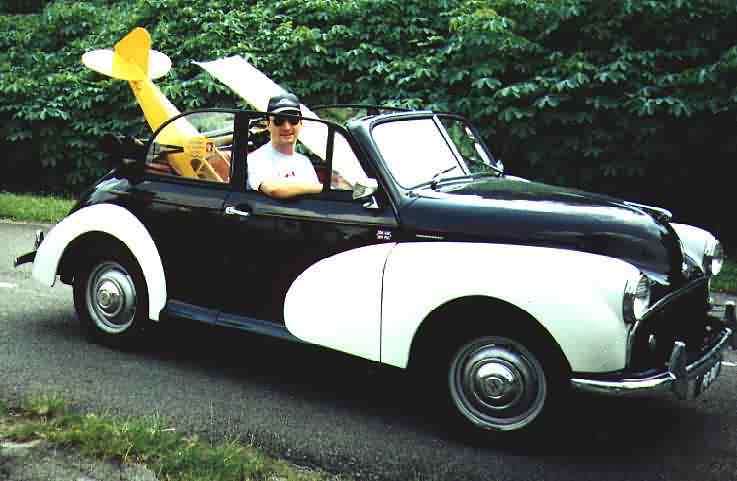
Morris Minor Corner
This is Moggy, who keeps me busy:
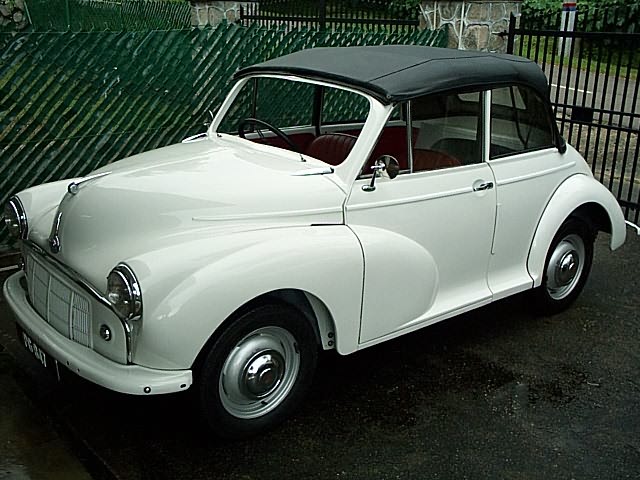
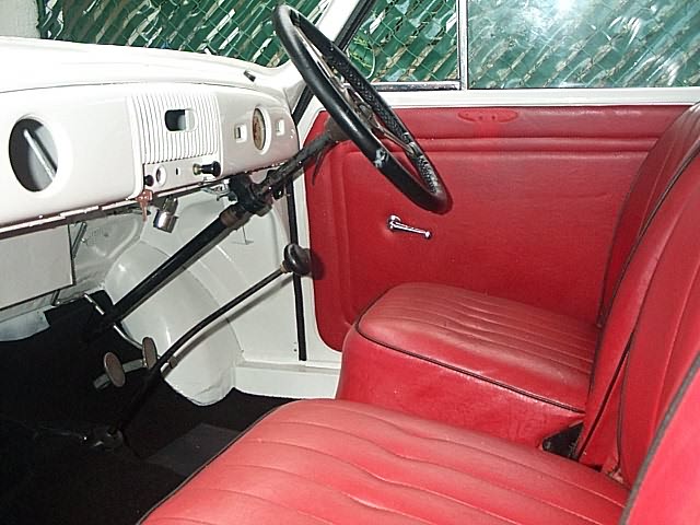
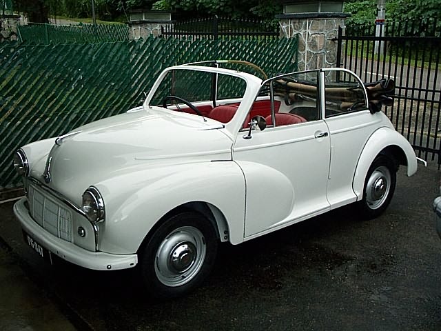
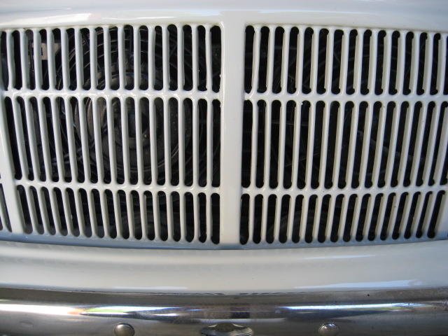
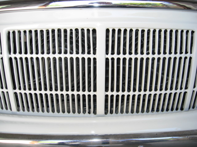
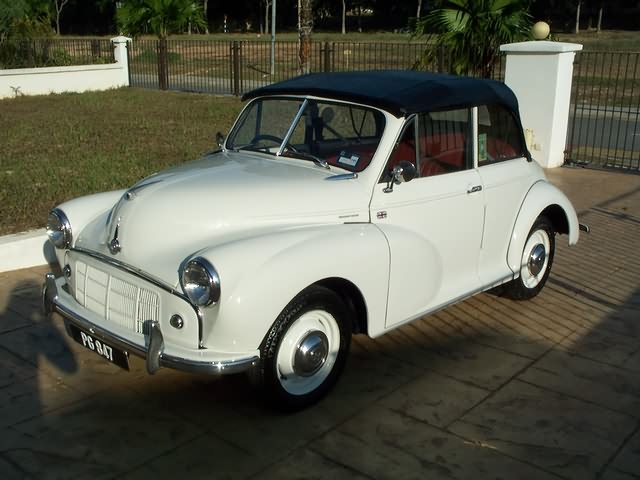
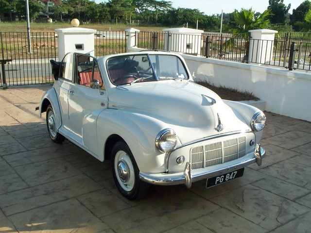
Morris Minor Tourer 1953
Split window
Right hand drive


Doesn't she look nice?
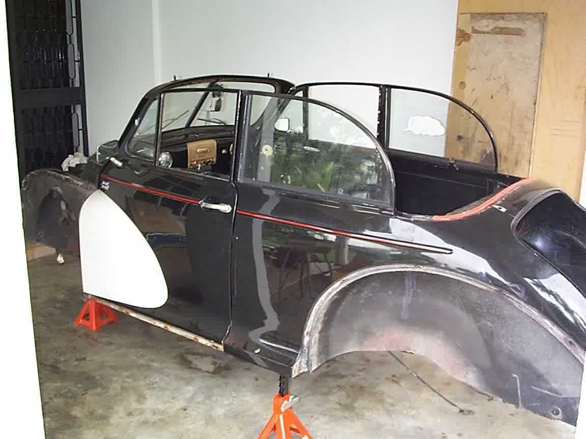
Part 1 - Purchase and wake-up
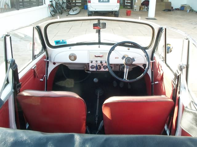
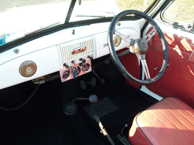
The Minor looked really nice when bought. Interior neat and clean, body
rust-free and only crying for a new spray-paint job.
First I only wanted to repair the obvious things and keep the car running. The
most obvious was an inactive front right brake. "No problem, only a stuck
brake-cylinder due to long standing" - I thought. Still in best mood, I
dismantled the front right brake.

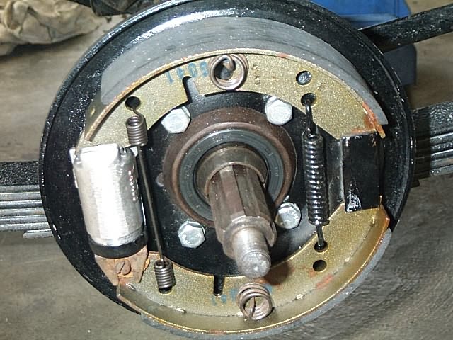
Where is the brake?
Diagnosis concerning the front right brake:
Brake drum turned out wide over limit, no more brake adjustment possible.
Both brake cylinders (Aluminium) heavily corroded inside. Furthermore somebody tried to knock one cylinder into place using a hammer, what resulted in oval deformation of the appropriate cylinder. As to expect, both cylinders were leaking significantly, what caused the a.m. brake-failure.
Outer wheel bearing loose in its fitting, what gives tremendous wheel-play.
Two break-springs overstretched.
Two days later
My spontaneous wish to learn more about the real condition of my car resulted in the restoration described below.
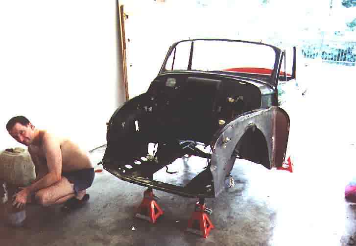
Part 2 - Searching for the substance
To keep a long story short, here is the breakdown of the major needed works:
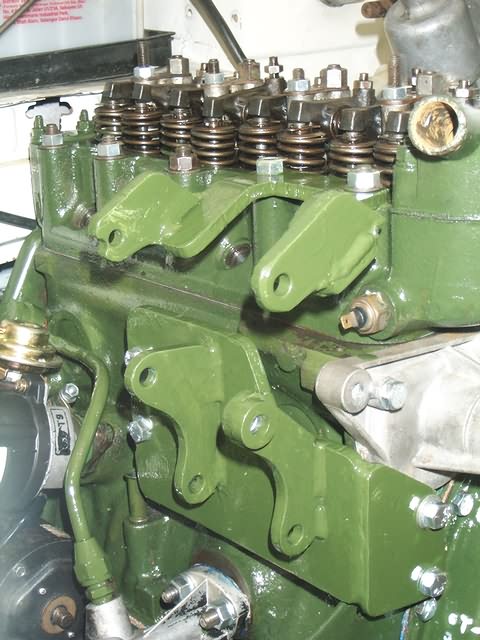
Engine: Crankshaft needs to be reground/new bearings (main and conrod). BTW: The original sidevalve-engine was replaced by a 1100 cc type, which gives the car that rocket feeling (short differential and gearbox), even at no oil-pressure.
Gearbox: not noisy, no jumping gears :-) , only a vibrating gearstick. Dismantling shows heavy wear on all gear-wheels :-(
Differential: same as gearbox. Driving ok, but looks ugly inside.
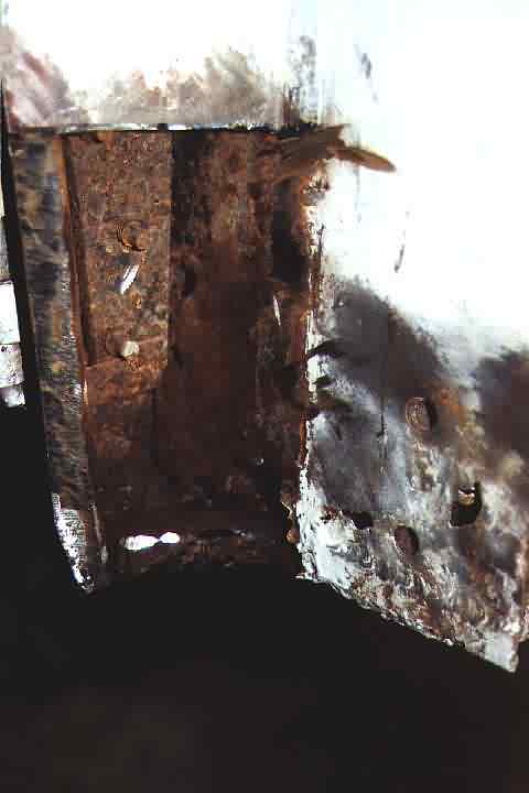
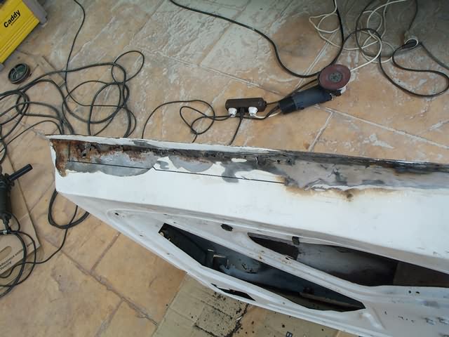
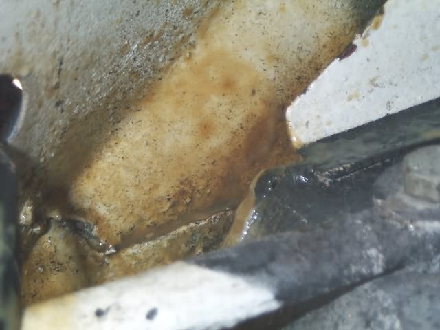
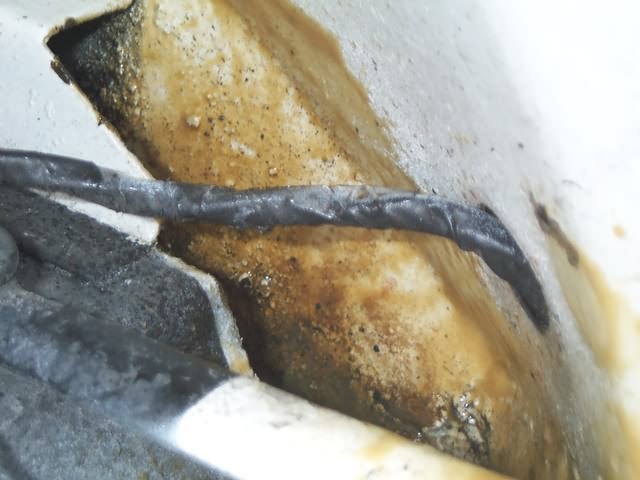
Body: Heavy corrosion everywhere, all structural sections have to be
replaced.
Part 3 - Let's get the baby back on the road
Waiting for the repair panels, already some minor stuff could be done:
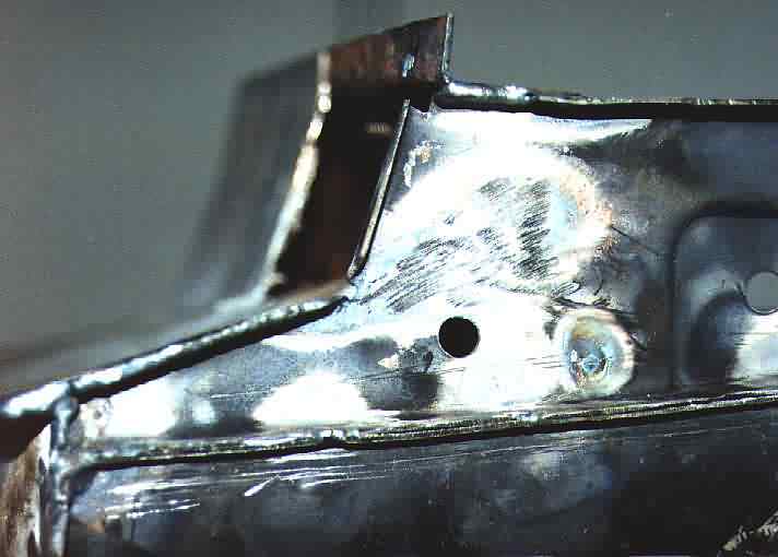
Lower a-column non-existent

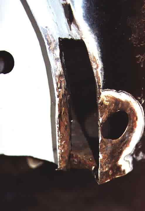


Common corner substance: rusty with holes nicely arranged in a package of putty
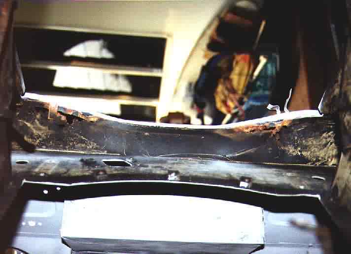
Upper front crossmember perforated by rust. This defect is typical and can be
avoided by drilling some drainage holes

Scratching old paint and tar and oil and grease can be fun - if somebody else
does it for you ;-)
The frame
A convertible shouts for a solid frame to avoid warping. Of course a welded
construction has to be flame-straightened before use:
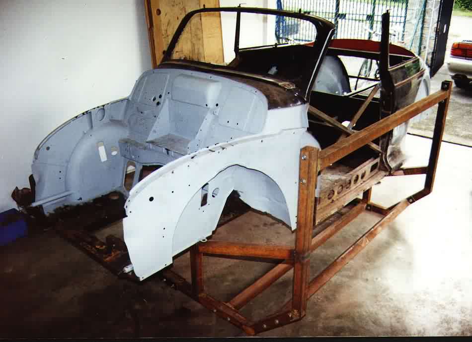

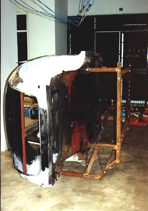
The frame allows tilting the car over to the side for having better access
to the bottom. Two main reasons for me:
1. No fun to wear full protective cloth in 32 deg C and humidity about 90%
2. I'm not that young anymore to crawl around under the car

I designed the front leg removable to being able to replace the longitudinal
member. The construction is screwed together where necessary to allow a mirrored
assembly (car can be tilted to both sides).
Finally on her side, Moggy reveals all her surprises:
panels
were already replaced (several times?). Obvious earlier procedure: cutting out
the old panels around the tunnel by flame-cutter, knocking in some new (or
similar) and weld the edge from the inside - at least that was done quite
nicely. Since nobody cared about the lower side of the panel, plates were
overlapping there between 0 and 3 cm. The panels were not rusted, so I decided
not to replace them. I only welded the edges on the outside. I hope to get rid
of this Frankenstein-outfit (so many scares) by a proper
grinding-job.

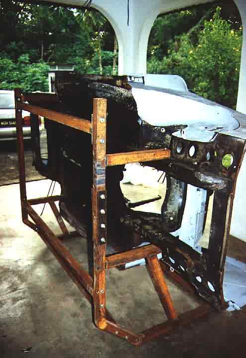
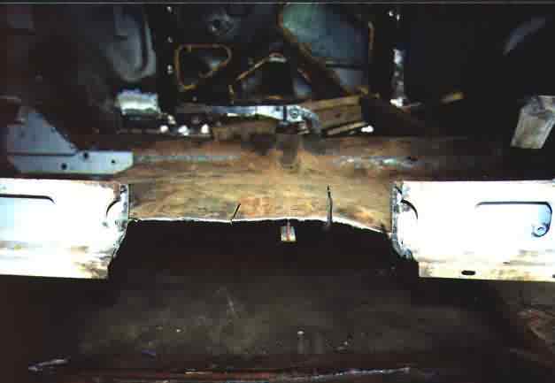
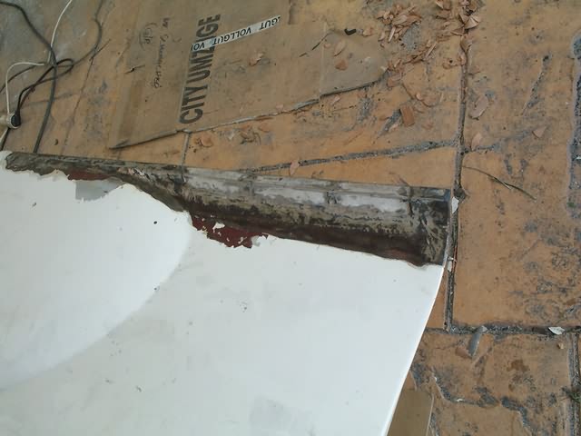
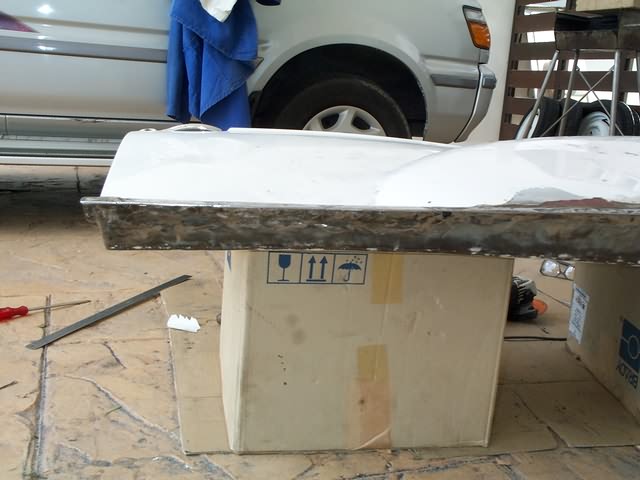
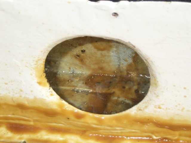
The rear end (trunk-bottom) needs replacement. Too many earlier trials to weld
back the thing. The most hollow sections created their own drainage holes by
rusting. I'll have to drill alotta holes to avoid this in future.

My personal favorite: the longitudinal members. bottom section AND around the
tiebone-fastener almost gone.
Once at this point, there is no way back. Until the ordered panels arrive,
there is enough time to do all the small-small repairs:


I don't want to mention all the individual holes, which had to be closed -
everybody can imagine.
Nov.99
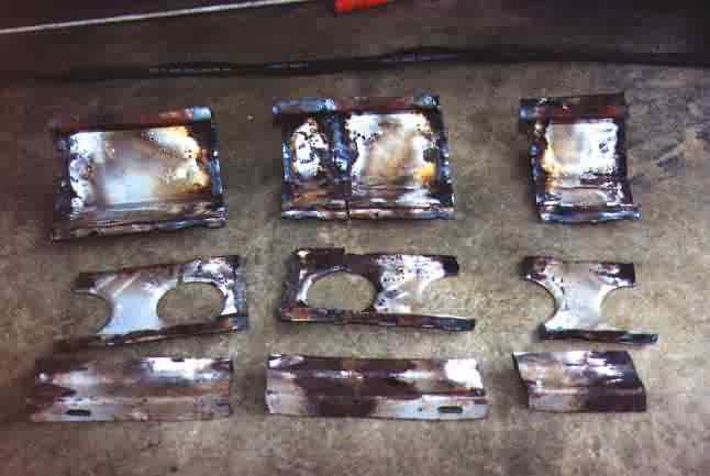
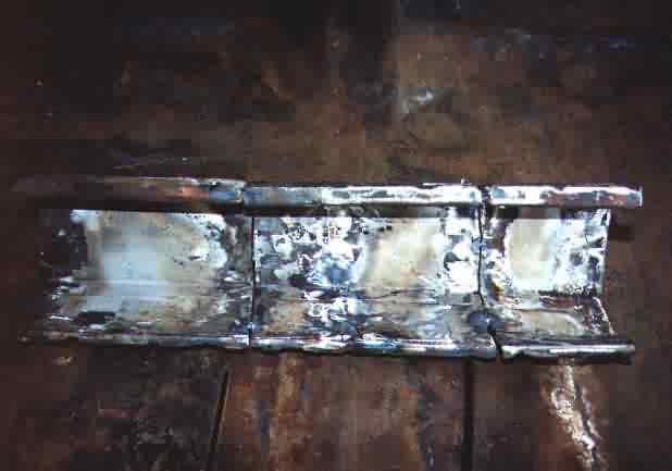
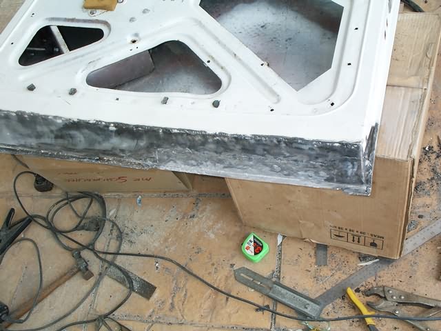
Once blessed with the right stuff, the whole program can be performed. Longitudinal members, entire sill section (6 panels per side), A and B column-base replacement.
First I strengthened the body by welding some angle-bars crossed into the door-sections. I replaced the members one by one and used my frame to maintain the alignment. Although I got some warping after finishing one side, it vanished again when welding the other side :-)
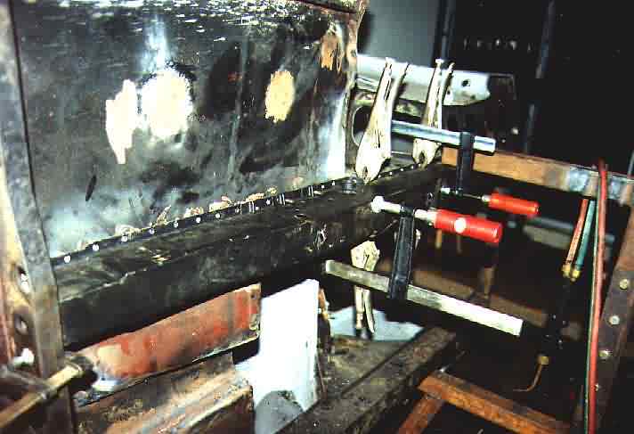

To avoid shrinkage, spotwelding with following hammering (as described below)
should be used. To achieve maximum strength and save weldings, the member-edges
should be drilled (about 7 mm) in 3 cm distances. It's important to align the
members by the holes, not by front- or rear end.
Then I fit in the inner sill sections (bottom plate). It's very important only
to tack-weld, whatever can be tack-welded. Longitudinal seams at this parts let
your car shrink by centimeters. If you cannot avoid long seams, proceed as
follows:
First tack weld the panel and go for a maximum distance between the weldings of
2cm. For all the imperial guys, that's less than 1 inch. Hammer the spots (by
counter-holding a heavy hammer) to equalize the shrinkage. Now the seam can be
welded very nicely. Hammer the whole seam. If you are lazy, there will be only a
Mini left from your Rolls. If you are Schwarzenegger, you can sell the car as
stretched Limo.
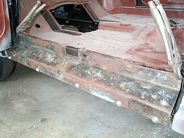
I left the crappy outer sill sections in as long as possible to check alignment
and shape. But you have to be careful not to follow any warped structure.
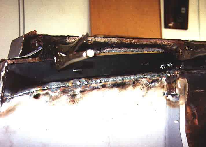
After replacing also the rear inner sill panel (the inner sill-panel came in two
pieces), its time to replace the outer sill panel (1 piece).
Remark:
Old boxing plate and inner sill box are not taken out yet. They are essential to
maintain at least some stability.

If the earlier performance was good, no unexpected problem should occur here.

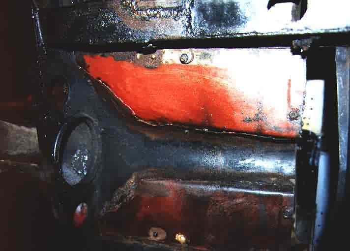
I couldn't resist to melt the edges of the front and read ends. Just looks
nicer. If you do this over the full length, you can be sure to get problems with
TUEV (German), MOT (UK) or Puspakom (Malaysia).
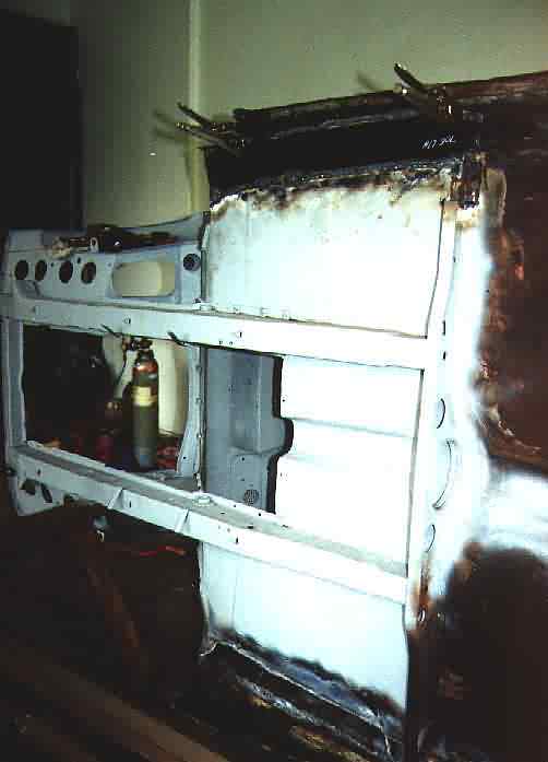
Now it's time to replace the lower a- and b-columns, if needed. I got ready replacement, but only needed a few centimeters.

Before cutting: Was repair really needed? - I don't know.
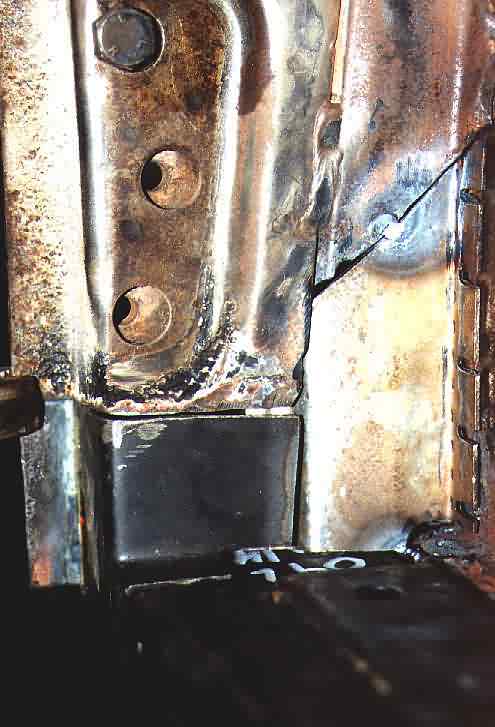
The inner section (here L/H) was custom-made. If you don't need more, also the
outer section can be manufactured easily. First fit in (tack-weld) all pieces,
then weld.
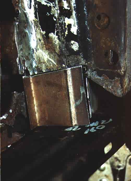
On the other side similar performance. Result is quite ok, isn't it?
Now boxing plate and inner sill-box (only one side) are removed and the rest
gets prepared to fit in the replacement.
Warning:
It took me more than one day per side to get the environment right.
The floor panels were between 1,5 cm to low (front of sill) and 2,5 cm to high (end of sill)

When stripping the edges, some more rust will be found. Time again for more
custom-made panels. This sections may not be underestimated, since they are very
important for stability (at least for the convertible).

This stiffener is only for the convertible. Should I mention that it was
forgotten anyhow earlier?
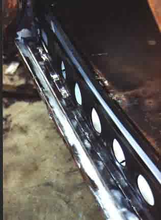
To bring all the sill-panels in, a certain order has to be obeyed:
First the stiffener (only Tourer), because it's placed partly under the boxing-plate. Don't forget to drill big holes for the drainage (before welding in) and drill enough holes for the tag-welding into the bottom section of the stiffener. Next the boxing-plate will be fitted in. If the preparation is ok, it should slide in anyhow. Last the inner sill-box finds it's place. Again don't forget to drill enough holes for tag-welding this thing to the stiffener, elsewhere the stiffener makes no sense.
No need to mention, that all tag-weldings get hammered.
<small break on>
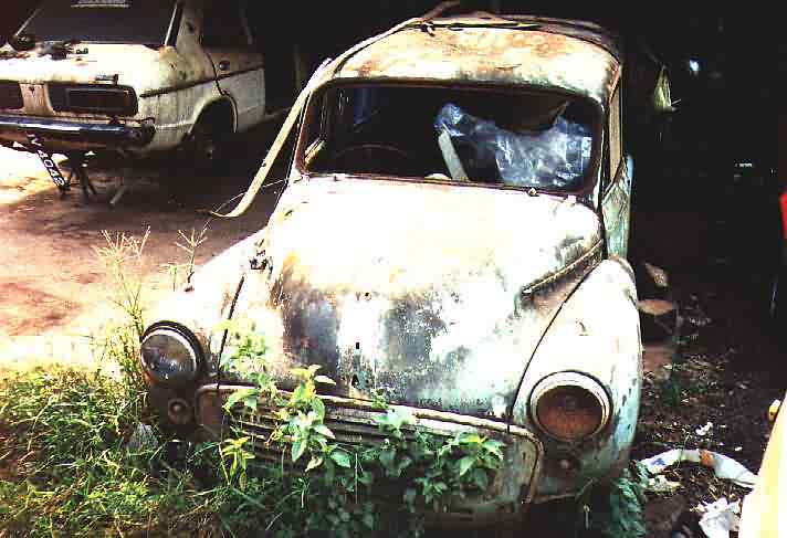


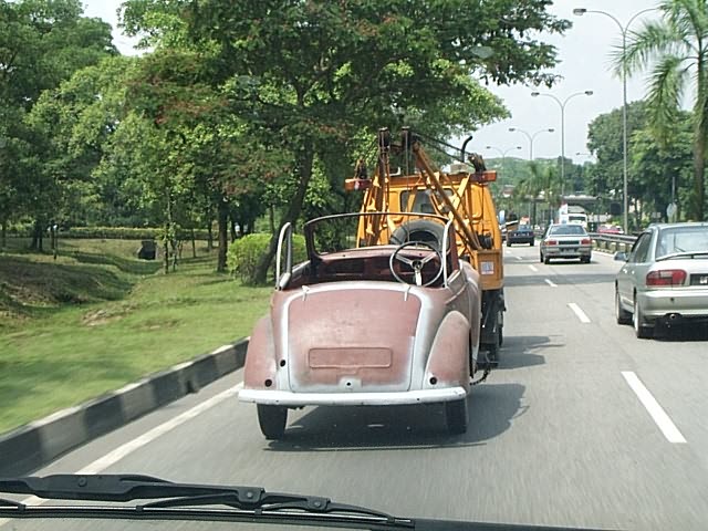
Found this Minor Traveller somewhere in center Malaysia. Needs only some polish ;-)
<small break off>
<Sidenote on>
During the last weeks I found the flame-cutting torch quite helpful. It's a
welcome alternative to the angle-grinder in many situations. Especially when
working in narrow corners or gaps, it's unbeaten.
I would be in favor of a small precision torch, anybody knows a source?
<Sidenote off>
Dec.99
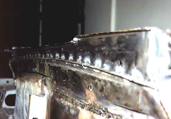
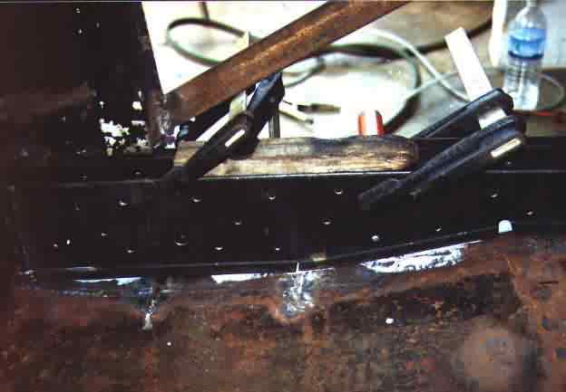
Next the boxing plate gets welded in. Make sure to align the plate with the
outer sill panels contour, elsewhere it will look extremely ugly later. For
better stability I tack-welded the boxing plate to the stiffener/inner sill
panel from the outside (after grinding some groves into the fold) and also from
the inside. This (invisible) welds can easily be applied through the big holes
(boxing plate) when using gas welding, but don't overdo, since they cannot get
hammered.

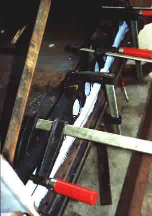

Now the inner sill box is placed in. Since we prepared the pieces very
carefully in advance, we don't have any problems to fit it in. A lot of F-clamps
are used to position the box exactly. Welding through the holes has to be
performed fast and hot. Fast to avoid shrinkage and hot to have a safe
penetration.
Of course MIG welding is the best for this job. Some people claim they can MIG-weld
through the upper panel without drilling holes. This might work in the car
industry, where conditions are perfect with no gap between the panels and so on.
In real life: forget it.
Again: don't forget to hammer all tack-welds when still hot (easier) to take out
the shrinkage.
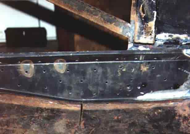

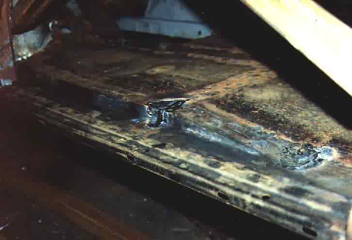
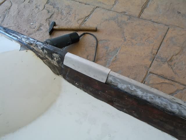
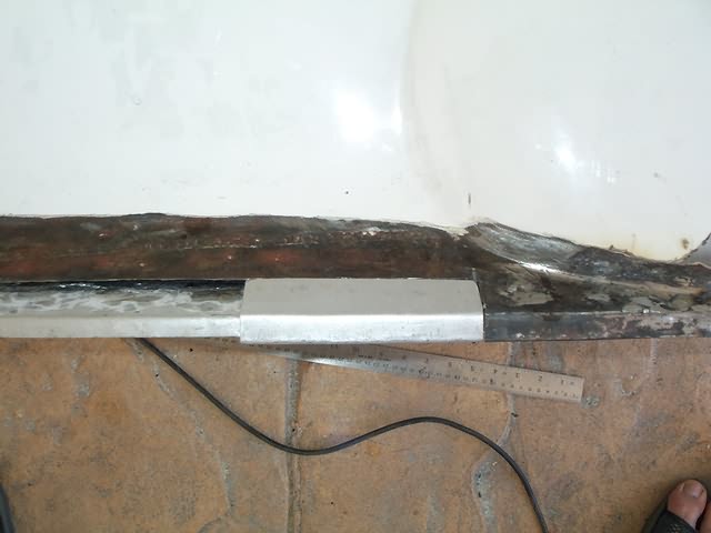
On both pictures you can see some heated locations, which appear greyish with
brown border.
What looks like a torch-accident, is a case of classic flame-straightening. I
was forced to straighten the right inner sill box, since it was warped obviously
due to manufacturer's fault.
Anybody wants to know some basics about flame-straightening? If so, I can throw in a basic seminar about the subject. Waiting for your feedback.

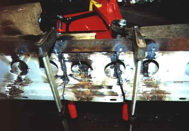
As mentioned earlier, enough welds should be performed for a proper bond between
stiffener and sill box - but seems that I did a little too much.
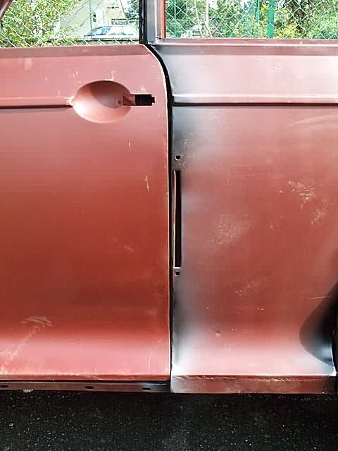
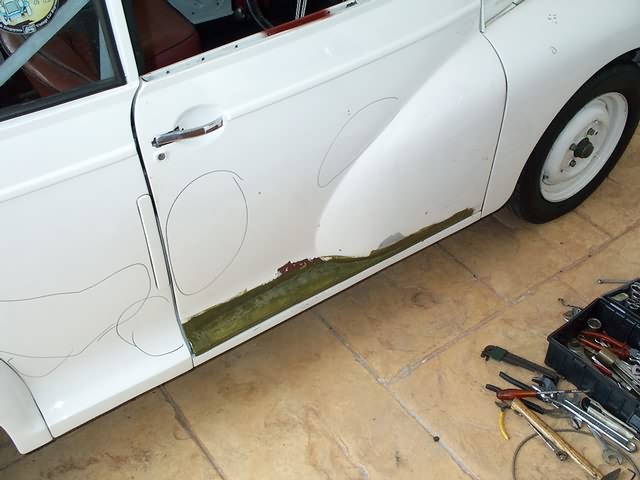
Now its time to remove the door-stiffeners and check the fit of the doors.
Since we worked very carefully, nothing should be warped and the doors should
fit in nicely, shouldn't they?
:-(((((((((((((((((((((((((((((((

On
the right side the door-gap closes to the top, but at least the lower gap is ok.
Although unexpected and a bit frustrating, a quick cut through the upper
sill-half with the hacksaw followed by highly sophisticated alignment (lifting
by jack) and re-welding the whole thing should solve the problem.
OK, said and done. The right side is ok.
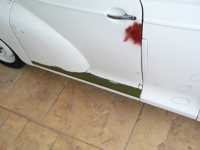
After having checked the left side I got this vision about a newspaper ad:
"Morris Minor Tourer, welding almost completed, for sale due to lack of
time. Doors are missing but should be available easily"
The left sill has shrunk significantly, so the door doesn't fit in at all. Beside this the door gap isn't parallel, which doesn't worry me further.
To the thousands of people, who follow my report in their restoration step by step: SELL THE CAR RIGHT NOW!!!
Short note to all those, who are a little behind in their restoration:
It seems that the excessive use of tack-welds forced this shrinkage, when
welding in the sill box to the stiffener. Additionally I wasn't able to hammer
most of the welds, since they weren't accessible through the boxing plate holes.
Finally my preferred gas welding is the most unsuitable welding application for
this job, since the welding takes a lot of time and the by-flame heats up a wide
area.
My advice: Use MIG here, less welds and try to place the welds accessible for
hammering.
After some beers I put back the advertising application form and think about a
technique to lengthen the sill again. Since I cannot hammer the whole structure,
I only can cut the whole sill section, stretch the sill and re-weld. Sounds like
fun, doesn't it?
Warning: The following procedure took two month, my good mood (ask my wife) and the nice look of the sill section.

The right side seemed easy to handle: Cut, stretch (car jack under sill) and
re-weld.

On
the left side the cut goes through the whole sill structure, since I have to
lengthen the whole thing and not only to bend.

A jack, supported properly, should have enough Ummph to stretch the sill.
But typically two problems occur:
In order to weaken the structure, a few heart-breaking angle-grinder cuts have
to be made. One parallel to the sill (elsewhere you try to stretch the bottom
panel) and one (or more) vertical to the sill to distribute the expansion to
several locations. BTW: The shown vertical cut wasn't long enough and needed
extension.
Warning: the following description doesn't lead to success, only to frustration. Don't try this at home.
Once the sill is stretched (check with doors), welding is performed :-) .
Back-check after cooling down: same as before - no door gap. WHAT THE HELL...???
This you repeat a few times (cutting, stretching, welding, checking, swearing).
How often, depends on how much you enjoy this game.
After two weekends I decided to change to the right strategy, but didn't know
yet what this could be. During the next weeks I tried:

OK, using TIG now there was some improvement, but still far away from
zero-shrinkage. So I continued that game welding, checking, swearing, cutting
for the next weeks until my left sill looked worse than the one I replaced
originally.
Frustrating, isn't it?
If the sill looks like this, its time again to search for the advertising
application form.
The tack-welded angle bar should prevent from shrinking. You can guess, whether
it worked :-((

If your sill looks like that, you are really desperate.

The positive aspect: Let's have a look at the sill structure. This shot you can
only see on JensSchumi's webpage. Or is anybody else so stupid to cut apart his
fresh restored sill?
Next step was to separate the panels again and work them over.
Reassembling the inner sill box, of course with large gaps. In this stage two
pieces (mid sector) were already welded and grinded. Welding seams at this
"unrestricted" section doesn't give you huge shrinkage, since the
whole section can expand when heated.

Welded in again with acceptable result.
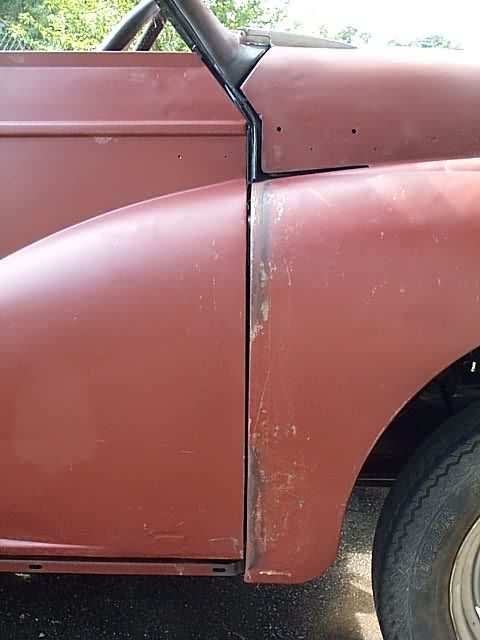
Meanwhile I developed a more sophisticated strategy to control the door-gap:
Make it as big as possible and don't even try to come out exact after welding -
THAT DOESN'T WORK, at least for me. You can shrink the section any time easily
by applying some heat, but you can never stretch it.

Finally the door-gap is correct, took "only" 2 month.
I didn't mention yet, that the right (formerly adjusted) door-gap was seriously
affected by the other side's activities and had to be rectified again. This
reminded me, that a convertible is a highly flexible thing, since the
stabilizing saloon's roof is missing.
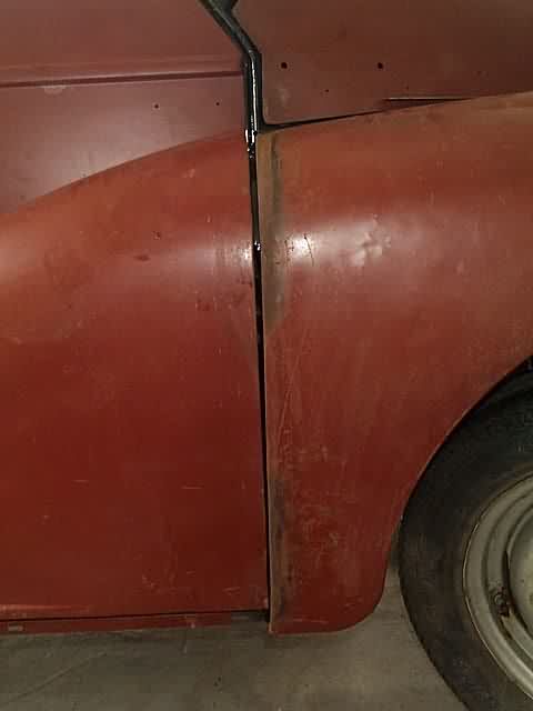
Also keep in mind that a convertible chassis can twist easily during the restoration. If you find the door corner standing out either at top or bottom and on the other side vice versa, you got some real problems. To check for twisting, make sure that the chassis is not forced or stressed by anything like support frame or standing on uneven stands.
Gallery
Since I'm short of time (as usual and btw, who isn't?), I decided to invest
more spare time into the Minor and less into writing. Therefore following a
picture gallery of the proceeding restoration. If anybody wants further info
about certain pictures or procedures, please email me. Sooner or later I will
finish the report in a proper way.


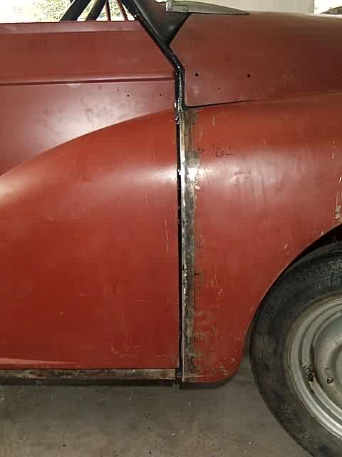
How to get the door gaps right


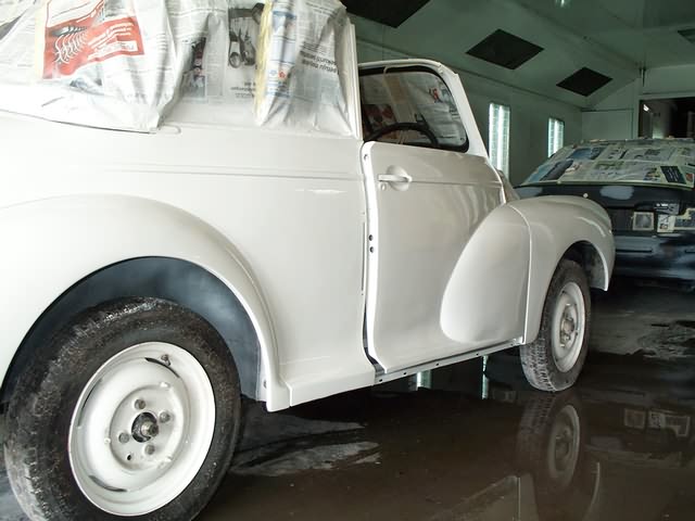
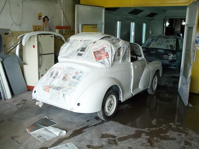
Ready for the spray-painter


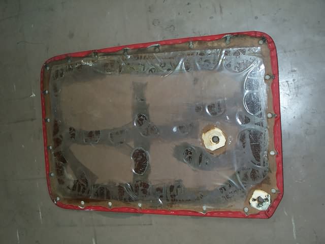
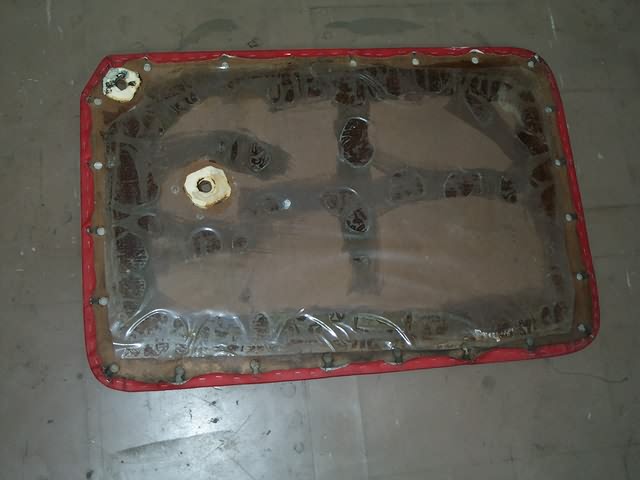
Front brake cylinders for the 1st series are rare and expensive (UKP 50 / pc.). I decided to repair the old cylinders by drilling them out and pressing in a stainless steel sleeve. This should last for the next 100 years or so :-)


Big moment at Schumacher's


OK, OK... I know...
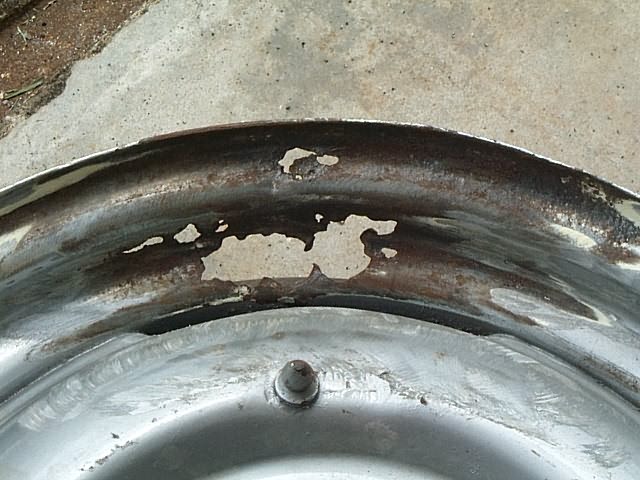
But no choice. I have to get the car rolling and there are no 1st series rims
available in Malaysia. Will get a fresh set from UK asap.


Almost finished
February 2002
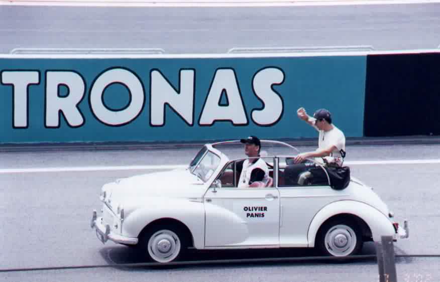
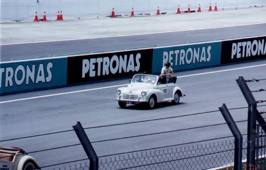
Petronas F1 promotion tour to Penang. Moggy got the award for the smallest and oldest joining car and also the car with the longest journey. Including a quick inevitable business trip mileage added up to 1800 km in three days. Beside a tire puncture no technical problems :-)

assembly at Sepang F1 Cirquit, Kuala Lumpur
wipers are in working condition, but anyway... it makes no
difference

reception at the Menteri Besars residence in Ipoh
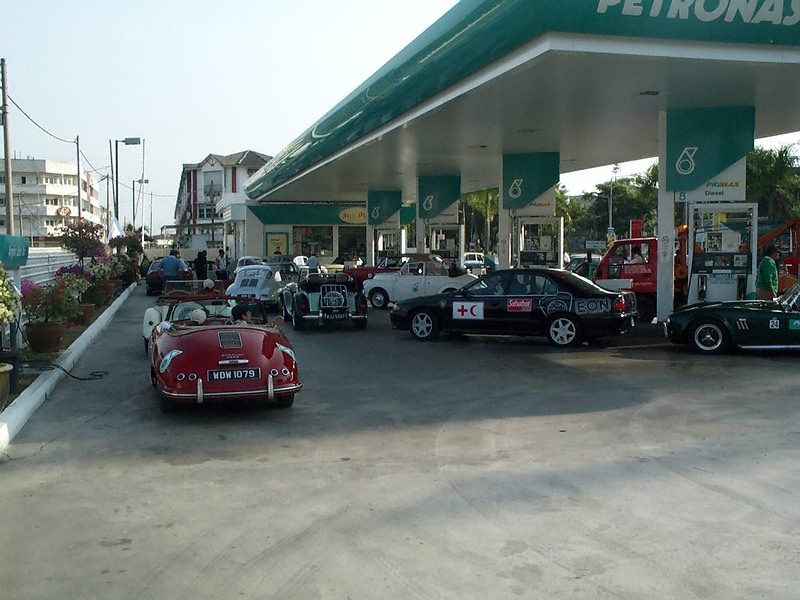
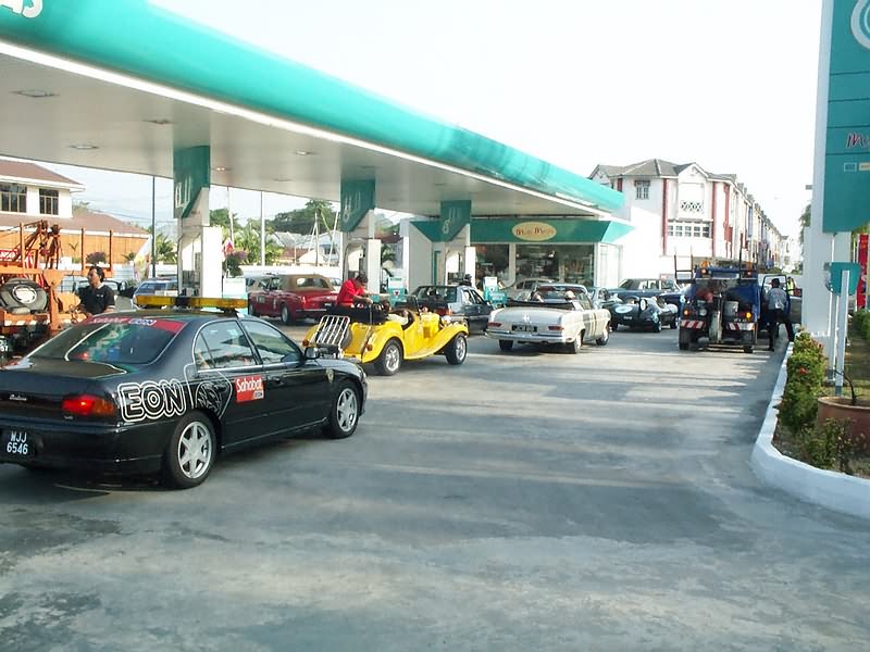
no Petronas station was ever that ravishing before
arrival in Penang, note the traditional dancers
Lucas, the Prince of Darkness stroke again. Fuel-pump this time
March 2002, F1 race in Malaysia - Drivers Parade

June 2002, The Johor Sultan's birthday


August 2002


Cleaning out the wheel arches thoroughly before applying black
undercoat

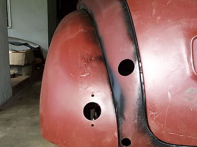
Cracks appearing on the front bonnet corner. Reinforced by silver-soldering in a
3.2 mm steel welding rod. You surely want to get a fresh spray-painting after
that.
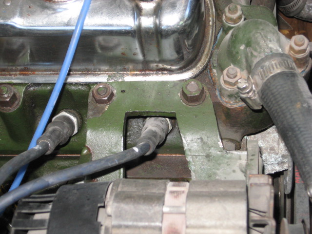
April 2003 - Electronic Ignition, Oil Filter, Fusebox
Time for some meaningful modifications. All of them are easily reversible.
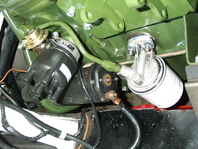
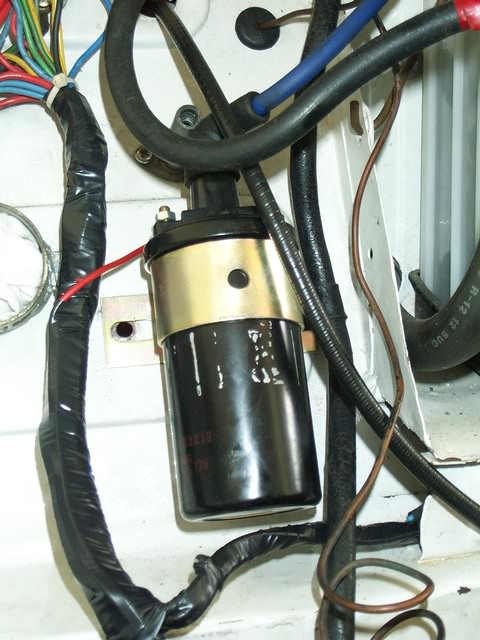
Electronic ignition, 3rd party accessory for Minis. Engine idles much
smoother and stronger now. Needs a high-power ignition coil though.
Oil filter from a Mini, no more leaking
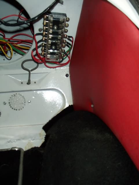
Not feeling overly confident about the 2-fuse solution by Lucas, prince of darkness, I installed a proper fusebox in the inside. The original fuse-unit remains in the engine compartment because of sentimental reasons ;-)
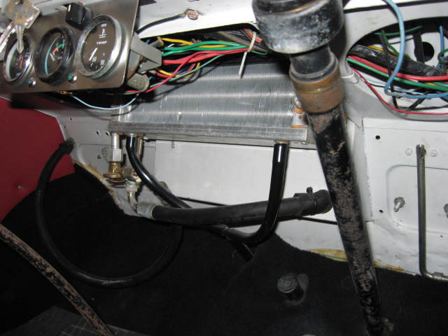
May 2003 - Airconditioning, ...
... since my family uses the car on a daily basis and does not like to get
fried with hood open...
It is a standard 3rd party aircond based on a Sanden compressor and a horrible
bulky evaporizer unit, which you could only install by sacrifising the use of
the passenger seat. I finally ripped out its guts and made a new casing from
Al-sheet, which fits nicely and invisibly under the center dashboard (pictures
later).
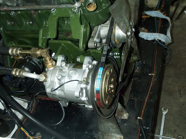
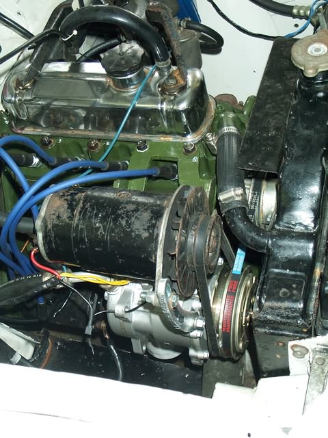
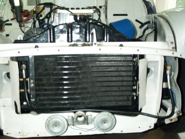
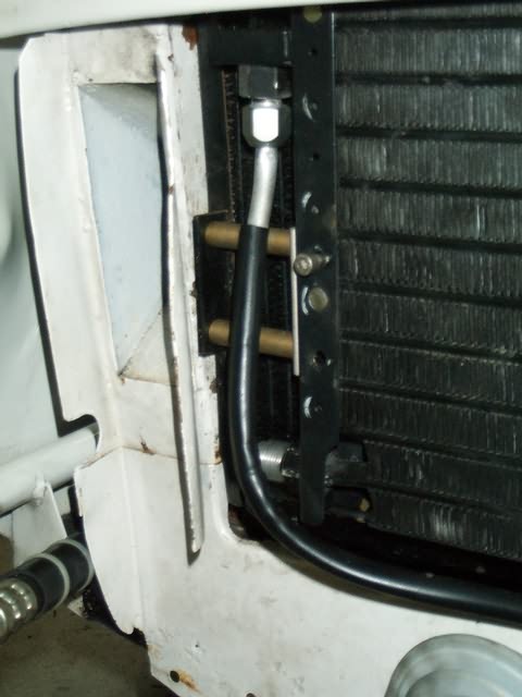
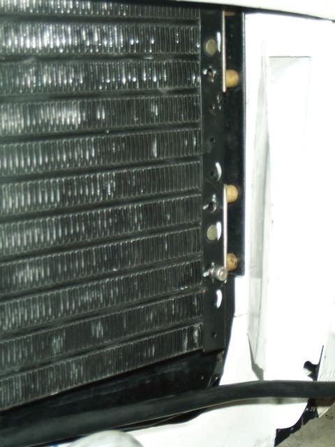
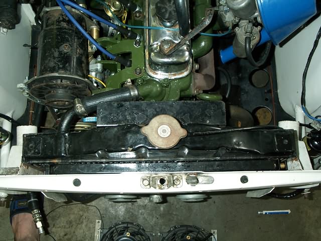


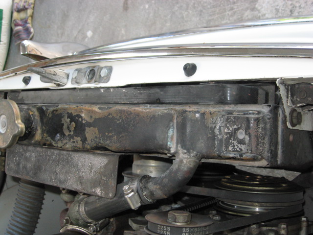


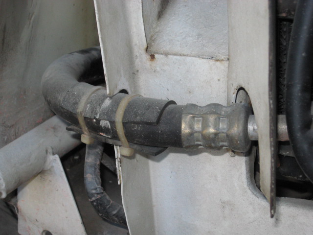
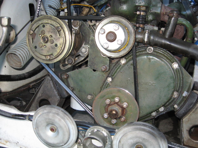
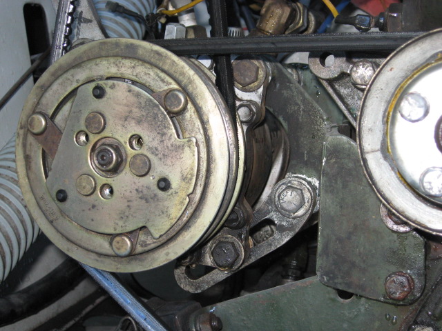
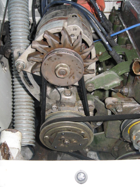

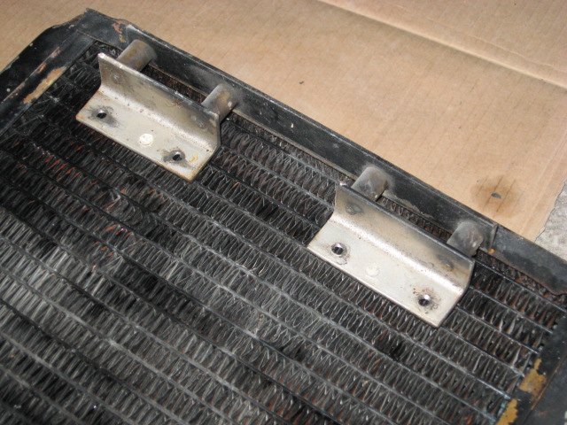
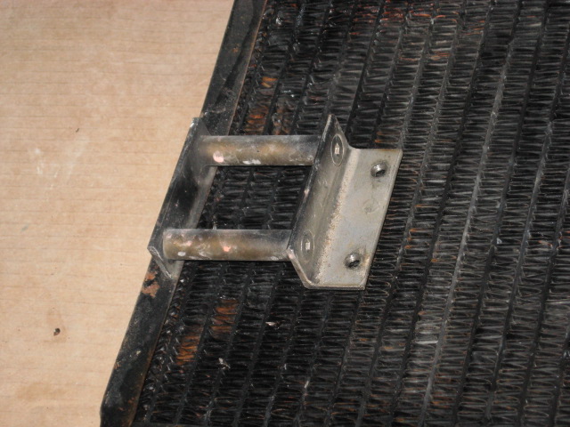
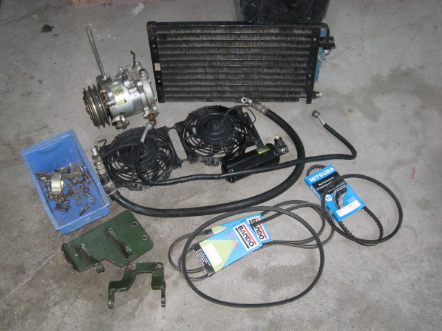


For installing the condensor I had to move the radiator back about 20mm, what leaves almost no space between radiator and fan. It is highly advisable to replace the original fan with a plastic unit (better efficiency and tolerance), preferrably with a ring on its circumfence. Depending on the temperature in your country you could also remove the fan completely since the additional electric fan might be sufficient.
I chose to settle for 2 small fans instead of 1 big unit, since I expected a more efficient cooling. As mentioned already earlier, space *is* an issue. I finally machined appr. 3mm off the fan-casing faces to get everything fit under the grill.
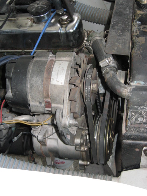
Shortly after the first test-runs I installed a Mini-alternator since the original 20A dynamo doesn't really cut the mustard.
May 2003
Theft protection during our overseas trip? - No problem :-)
March 2005 - Gearbox
If you haven't done recently, crawl under your gearbox and check whether the screw, which secures the reverse-gear shaft, is tight.(Sidenote: don't strip the thread while checking).
Why you should do that?
This friggen screw came loose and fell of.
The reverse gear shaft, which is held on both sides by a seat in the gearbox
casing, slipped out of one of those. Once the shaft got side-load (by shifting
into reverse gear) the other seat broke away :-(
Unluckily the original gearbox is a 'smooth' type, which is very rare already
and the chance to find one here in Malaysia would be zero for sure.
Apparently my gearbox was an even rarer case, since it fits straight on the
1098cc engine. I reckon that my 1953 Tourer is one of those few series 2 Minors,
which were first equipped with an OHV engine on the old drive-train. Any further
information on that would be highly appreciated.
Due to lack of options the decision was made to convert to a later ribbed unit but keep the early gearlever concept, i.e. the long gearstick instead of the later remote with short and vertical lever.
Main problem occuring was that the guts of the later box are appr. 3mm longer.

Above picture shows the rear main bearing in its holder. The left (later)
holder has an protruding collar, which fits into a recess on the later remote.
Unluckily the older remote does not have that recess so I needed to modify the
design in a way that the collar is gone.
I was able to get a bearing 3 mm thinner than the original unit and the
circlip-groove milled into. Since the chosen bearing has a smaller OD, I had to
braze a brass-ring into the holder and subsequently machine it to proper
fit.


The picture shows a ZZ-bearing .ZZ means dust-covers on both sides, which have to be removed before comissioning.
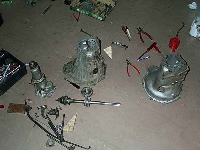
There are some other things to modify, but nothing serious.
One thing for sure: after that you *know* how to dismantle/assemble a Minor
gearbox.
May 2005
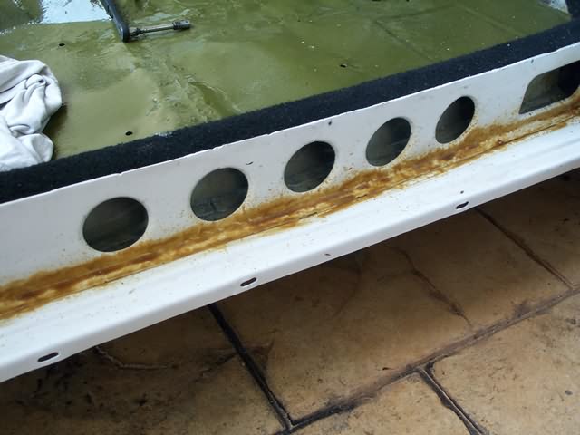
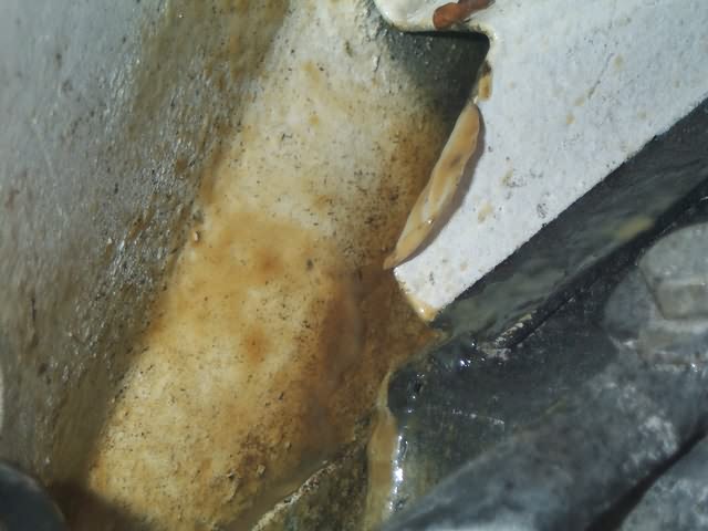
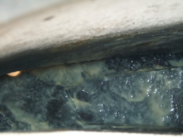
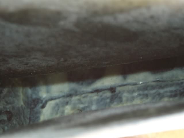
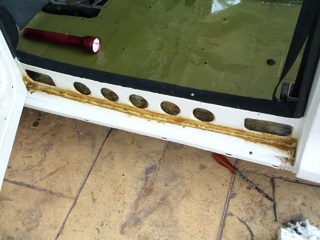
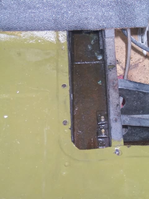
I knew already since quite some time that there was trouble waiting inside the doors (rust). At the same time the paint was developing bubbles allover the body, due to lack of thoroughness by the former spray painter (painted over moisture soaked putty w/o drying before).

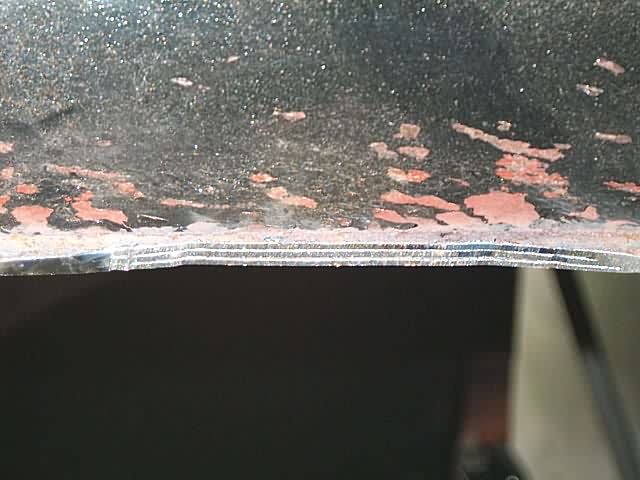
Pinholes on the top, big holes on the bottom
Been there, done that, got the T-shirt.


Off we go - to the spray-painter.


June 2005

Once back, right away a fresh panel coating.

In order to keep the hollow sections from rusting for the future, I used a system of chemical de-ruster and wax from Germany. More info, even in English, at: http://www.fertan.de/fertan.com/en/index.html


I'm pretty sure that there won't be any rust problems over the next few decades :-)
Once on it, I restored the door-covers which were seriously rotten due to insufficient plastic covering on the inside.


Looking better now, eh?


